
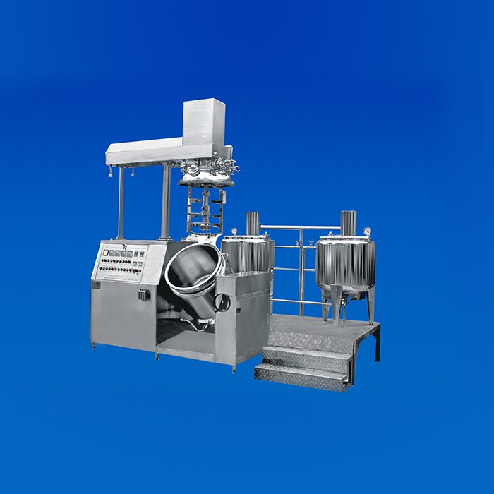
KFJ-500 Vacuum Emulsifying Mixer(Emulsifier)
(This picture provided is only for reference, the final appearance is based on real product.)
I. Electric control system (PLC touch screen control)
")
")
Touch screen control
1. Adopting German Siemens S7-200 series.
2. Touch screen adopts Siemens Company Model: TP700, 7inch
3. On the touch screen, it is possible to adjust and vision mixing speed, temperature of each jar, set upper limit and lower limit of temperature, control automatic valve. It is possible to set the time control for slow speed emulsifies mixing and control performance of lift of hydraulic system.
Electric elements: Siemens products
Transducer: Panasonic Company
Button/switch: Fuji Company
Ⅱ. The description, appearance and instruction of model KFJ-500machine.
2.1 Model KFJ-500 Electric control system for Vacuum Emulsifying Mixer(Emulsifier)is a coaxial and triple type mixer, suitable to stable homogenizing and emulsifying, the finished granular is very small. The quality of emulsifying depends on dispersing of the granular on the preparation stage. The smaller the granular is, the weaker the trend of accumulation to the surface becomes, thus the smaller the opportunity for the emulsifying to be broken becomes. Relying on mixing of reversed impeller, under the condition of homogenizing turbine and vacuum status, you can get the high-quality effect of emulsifying and mixing.
2.2 Model KFJ-500 Electric control system for Vacuum Emulsifying Mixer(Emulsifier)has very good performance in the aspect of insuring high quality of the finished material.
2.3 Instruction of machine
Model KFJ-500Vacuum Emulsifying Mixer is specially designed by introducing foreign updated technology and on the basis of ointment-making technics for processing cosmetics and ointment. It is composed of pretreatment boiler, vacuum emulsifying mixer boiler, vacuum pump, hydraulic system, tilting system, and electric control system, etc.
3. The basal equipment of machine body and technical parameters
The whole equipment of this system is composed of parts below: emulsifying mixer boiler, vacuum system, hydraulic system, electric control system.
3.1 Emulsifying mixer boiler:
Working volume: 500 L, material: SUS316L stainless steel, steam heating and water-cooling
Structure: With 3-layer structure, upper and lower end sockets. The upper end socket is connected to the tank body with flange between them. The internal layer of tank body is made of 5 mm thick SUS316L stainless steel and interior polished in 400 MESH (sanitary level). The middle layer of tank body is made of 4mm thick SUS304 stainless steel and can stand max working pressure 0.09 MPa. The external layer of tank body is made of 2 mm thick SUS304, and exterior polished in 300 MESH (sanitary level). All the welding seams shall be polished after rubdown, and as to the treatment interface, turned over edge arc transition is adopted. The heat preservation layer is made of PU polyurethane foaming.
In the tank, there are 3 mixers:
3.1.1 Cutting and vortex emulsify mixer: 7.5kw, 1150-3500 rpm (frequency control)
3.1.2 Low-speed frame type scraping mixer: 2.2kw, 10-40 rpm (frequency control)
3.1.3 The motor of Low-speed converse mixer and low-speed frame type scraping mixer is the same with speed 10-40rpm.
3.1.4 Attached units of the tank: Liquid feed inlet with stainless steel pipe filter, solid material inlet, vacuum inlet, compressed air inlet, breaking vacuum inlet, sight glass, temperature sensor, CIP cleaning head, discharging hole, dustproof asepsis respiratory device.
3.2 Pretreatment boiler:
Oil boiler of 300 L and water boiler of 400 L one each, material: SUS316L.
Structure: open (half-open) type, three feet with mixing.
Detailed Technical requirements:
Effective volumes: oil boiler of 300L, water boiler of 400L, material: SUS316L, 3 layers structure. The material of the inner of tank body is made of 5mm thick SUS316L and interior polished in 400MESH (sanitary level). The middle of the tank body is made of 4mm thick SUS304 and can stand max working pressure 0.09 MPa. The external layer of tank body is made of 2mm thick SUS304 and exterior polished in 300MESH (sanitary level). All the welding seams shall be polished after rubdown, and as to the treatment interface, turned over edge arc transition is adopted. The heat preservation layer is made of PU polyurethane foaming. In the tank, there is a turbine mixer, 1.5kw reducer and 960 rpm inlet rotary speed. Discharge hole is equipped with butterfly valve of sanitary level and pipeline.
3.3 Vacuum system
Adopting vacuum pump with Feilitong or Zhuoxin, air extraction capacity 106M³/h and motor power 3.85kw.
3.4 Hydraulic system
Composed of oil cylinder, solenoid valve, over-fall valve, oil box, and pressure- keeping valve.
3.5 Electric control system (A、Button control, B、PLC touch screen control)
A. Button control
Electric elements: Siemens products
Transducer: Panasonic Company
Button/switch: Fuji Company
Instruments and sensor are home high quality products .
It is possible to adjust and vision mixing speed , temperature of each jar, set upper limit and lower limit of temperature, control automatic valve. It is possible to set the time control for slow speed emulsifies mixing and control performance of lift of hydraulic system.
B. Touch screen control
1. Adopting German SiemensS7-200 series.
2. Touch screen adopts Siemens Company Model: TP900
3. On the touch screen, it is possible to adjust and vision mixing speed, temperature of each jar, set upper limit and lower limit of temperature, control automatic valve. It is possible to set the time control for slow speed emulsifies mixing and control performance of lift of hydraulic system.
Electric elements: Siemens products
Transducer: panasonic Company
Button/switch: Fuji Company
4. Technical Parameters of whole machine
4.1 The whole volume of container: 600 L
4.2 Service volume of container: 500L
4.3 Min. output: 300L
4.4 Equipment height: 2750mm (with cover close)/4000mm (with cover open to the upper limit)
4.5 Net weight: 2900kg (only for standard equipment)
4.6 Container: connected with vertical and protruding flange with leading edge, equipped with double jackets.
4.7 Heating: by letting the steam into the double jacket.
4.8 Service modes of container: atmosphere / vacuum
4.9 Base of container: welded and high-grade mirror polish.
4.10 Upper cover: flanged and liftable.
4.11 The speed of slow-speed mixing system: 10-40 rpm, 2.2kw (frequency control).
4.12 The speed of high-speed homogenizing-mixing system: 1150-3500 rpm, 7.5kw (frequency control)
4.13 Installation power of vacuum pump: 3.85kw
4.14 Main installation power: 17kw (only for standard equipment, no other option)
4.15 Electric power: 380±10 V, 50 Hz.
4.16 Allowable fluctuation of voltage: ±5%.
4.17 Low voltage control: 24 V
4.18 The water consumption of hydraulic ring vacuum pump: 4 L/min
4.19 Adjustable height of machine frame: ±10mm
4.20 The air suction device for ventilating motor
4.21 Security protection at low-voltage of 24 V
4.22 Equipment is made according to GMP standard.
4.23 The machine body is fully made of stainless steel SUS304.
4.24 All parts contacted with material are made of stainless steel SUS316L and mirror-polished.
4. Application, characteristic and advantage
4.1 Application
This unit can be used for production of ointments and creams in cosmetic and pharmaceutical factories, especially for the preparation and emulsification of ground substance with large viscosity and high content of solid.
4.2 Characteristic
This unit has such features as simple operation, stable performance, good homogenization, high production efficiency, convenient cleaning, reasonable structure, small floor space, and high automatization etc.
4.3 Advantage
This unit applies upper coaxial triple type mixer and hydraulic lifting mode to open the cover. The speed of rapid homogenizing mixer is 1150-3500 rpm (frequency control); the speed of slow-speed scraping mixer is 10-40 rpm (frequency control); the homogenizing head applies high cutting eddy current type emulsifying mixer. The slow-speed scraping mixer automatically abuts closely to the bottom and wall of boiler. By applying vacuum sucking, this unit can suck in powder material by using vacuum to avoid powder flying upward. The whole process is performed under the vacuum condition in order to keep from the production of air bubble after the material is mixed at high speed and up to hygienic asepsis requirements. This system is equipped with CIP cleaning equipment. The parts of container, which contact the material, are made of SUS316L and inner surface mirror polish is up to 300MESH (sanitary level). In order to ensure stability of control part, the electric control parts apply the products from German Siemens, the press key from Japan Fuji Company, frequency converter from Panasonic Company, and vacuum pump from feilitong. The unit is made completely in conformity with GMP and is the most advanced, ideal ointment and cream production equipment currently in China.
Ⅲ. Description of whole machine
1. Low speed mixing system
1.1 Two reversed low-speed mixing systems are composed of a hanging bracket full of scrapers as well as intermediate impeller.
1.2 The full automatic movable scraper's surface is made of PTFE, only working under the condition with material. It's easy for disassembly and cleaning.
1.3 Dynamic balancing coaxial shaft
1.4 Outer hanging brackets and inner impellers are made of stainless steel SUS316L.
1.5 The timing is controlled by PLC to facilitate the setting of working time. The mixer will not work if the time is not set.
1.6 The speed of the equipped reducer motor can be controlled directly by transducer to0-40 rpm.
1.7 The low-speed mixing system produces two independent countercurrent flows inside the material.
1.7.1 One vertical fluid along the center can force material flow to the bottom of container. Its function is to convey the material to the bottom of homogenizing-turbine rapidly.
1.7.2 Another circle flow forces the material encircle the inner wall of the mixing container to facilitate the material to make heat-exchange during heating or cooling stage, which can prevent the material from being damaged due to overheat or overcooling.
2. High speed homogenizing mixing system
2.1 High-speed homogenizing-mixing activity is accomplished by one turbine installed on the center bottom of tank.
2.2 Turbine is composed of dentate stator and rotor with impeller.
2.3 Turbine is made of stainless steel SUS304 or SUS316L, rotating parts pass the dynamic balancing coaxial shaft.
2.4 The timing is controlled by PLC to facilitate the setting of working time. The mixer will not work if the time is not set.
2.5 Adjust speed by frequency control: 1150-3500 rpm
This kind of structure i.e. executing on the turbine not from the bottom can assure high cleanness of the process project. The reasons are as follows:
a. The material will not be polluted without the influence of motor flange connection.
b. Turbine is made easy for cleaning, maintenance, assembly and disassembly.
c. The bottom of tank is completely smooth without connection and is easy to clean.
d. Assemble a central valve for discharging.
e. The mixing and homogenizing motors are installed on the top of the tank, which is far from the processing area.
f. Strictly ensure the safety of the operators.
3. Heating/cooling system
3.1 Heated by the steam in the double jackets.
3.2 The temperature of material in the container may be controlled through temperature sensor signal from the control panel.
3.3 Temperature control is composed of PLC temperature module and temperature sensor installed at the bottom of the tank. Actual temperature of material may be read correctly.
3.4 Cooling is directly accomplished by the external cold water through the jacket.
4. Vacuum system (-0.09Mpa)
4.1 Liquid ring vacuum pump is equipped with solenoid control valve at the water entrance.
4.2 Vacuum gauge indicates the vacuum in the container.
The vacuity may be set by using the vacuum gauge with max. value and min. value.
4.3 Vacuum safety switch is designed to keep the upper cover from opening at the state of vacuum.
4.4 Airtightness of upper cover is ensured by the silicon filling material on the flange.
4.5 Theoretically, max vacuity is 730 mm/Hg at 20℃. In order to get optimal emulsifying result, air mustn't enter into the material. For the process under vacuum condition, liquid or powder can be added to the container directly.
5. Upper cover lifting system
The lifting of upper cover is fulfilled by a series of hydraulic devices. The device is fitted with a safe limit system, which can keep the upper cover stopping at any expected position.
6. Tilting system of container (by manual)
Tilting system of container used for discharge is accomplished by a series of mechanical devices and stops at any angle.
7. Feeding system
7.1 Directly add the material to the tank after opening the cover.
7.2 Under the vacuum condition, the material will be absorbed into the tank by the suction valve through the strainer. Under the vacuum condition, the additive (powder) will directly enter the turbine through the hoper for excipient and additive mounted on the upper cover or the valve at the center bottom of tank so as to shorten the dispersing time.
8. Discharging system
8.1 Discharge the material from the container.
8.2 Discharge the material by compressed air to positive pressure. (pressure less 0.09Mpa)
8.3 Discharge through cam rotor pump.( extra purchase)
9. Process system
Observation window is equipped with wind board and lamp with good inner visibility.
10. Safety system
10.1 If the upper cover is not completely aligned with the container without enough tightness, stop using it.
10.2 If the upper cover is not perfect in conformity with the container, the discharging performance stops.
10.3 If the upper cover is not lifted entirely, stop using tilting function.
10.4 When the upper cover is open, stop using the mixing and homogenizing motors and vacuum pump.
10.5 Limit micro switch automatically executes the ON/OFF of the upper cover.
Note: Different parameters can be altered to the request of users to reach optimal performance.


 Seamless Soft Capsule Encapsulation Machine")


 ketchup production line
 Acceptance inspection--Russian Client
 2011 FCE


Copyright © Liaoyang Korican Machinery Co., Ltd. All Rights Reserved
Sitemap | Technical Support: 


